On this page
What is the Baffle Tool?
Our mouthpiece builder lets you design any mouthpiece you want, but it doesn't tell you what to make. A good place to start is the mouthpiece you already play. The baffle tool lets you measure its interior geometry and bring that into the design tool as a baseline. Instead of designing from scratch, you can start with something familiar and change only what you want to.
Assembly
Download all print files and follow the instructions on the baffle tool Printables page.
There are four things you need to print, in order:
- Printable tip opening gauge
- Everything in
partsfrom the baffle tool Printables page Tolerance_test.stlfrom the baffle tool Printables pageSlider block(after you follow the instructions below to determine which one to print)
Print settings to apply to every step:
- ~0.1 mm layer height
- 3+ walls
- 15% Gyroid infill (seems to result in less warping)
- Use a brim if you experience any warping or detaching.
- PETG
- Supports: on for the slider block, off for everything else.
- Orientation: keep the file in the same orientation it loads in the slicer.
1. Make the 3D Printed Tip Gauge
Follow the instructions here to print and assemble the 3D-printed tip gauge. This tip gauge is the measuring device for the baffle tool.
2. Calibrate Printer Tolerance
The printed tip gauge bar should slide onto the other parts with as little play as possible.
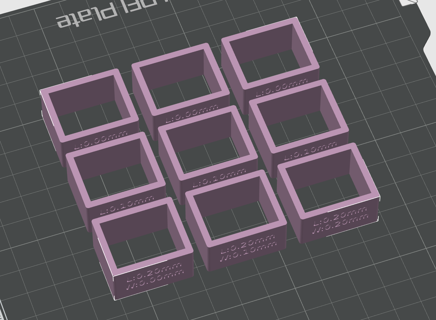
To do this, print the parts from tolerance_testing.stl. These hollow rectangular blocks are labeled by their tolerance size. For example, in the block labeled L: 0.20mm W: 0.10mm, the internal length and width increase by 0.20 mm and 0.10 mm, respectively. The ideal tolerance size is one where the bar slides with slight resistance but no wobble.
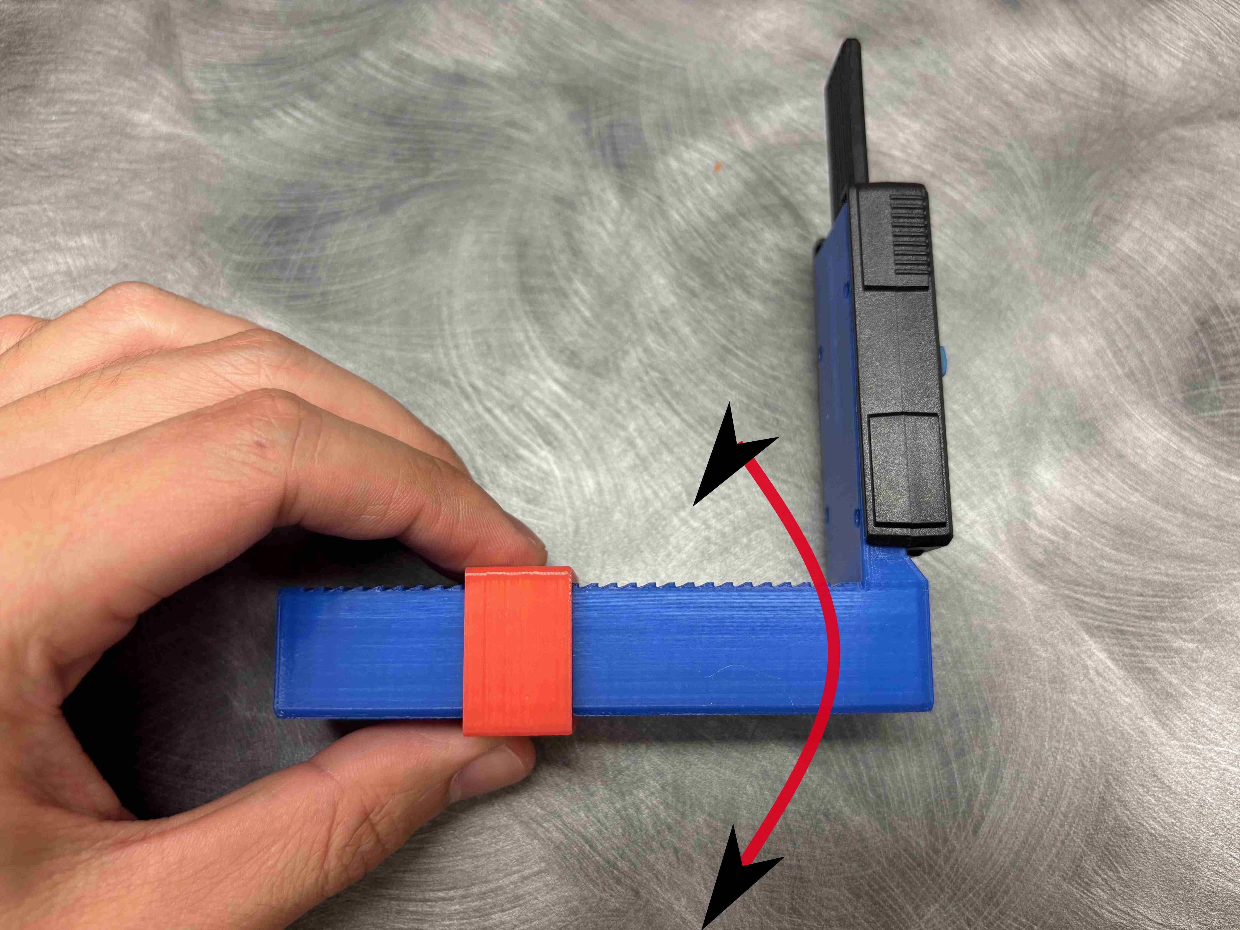
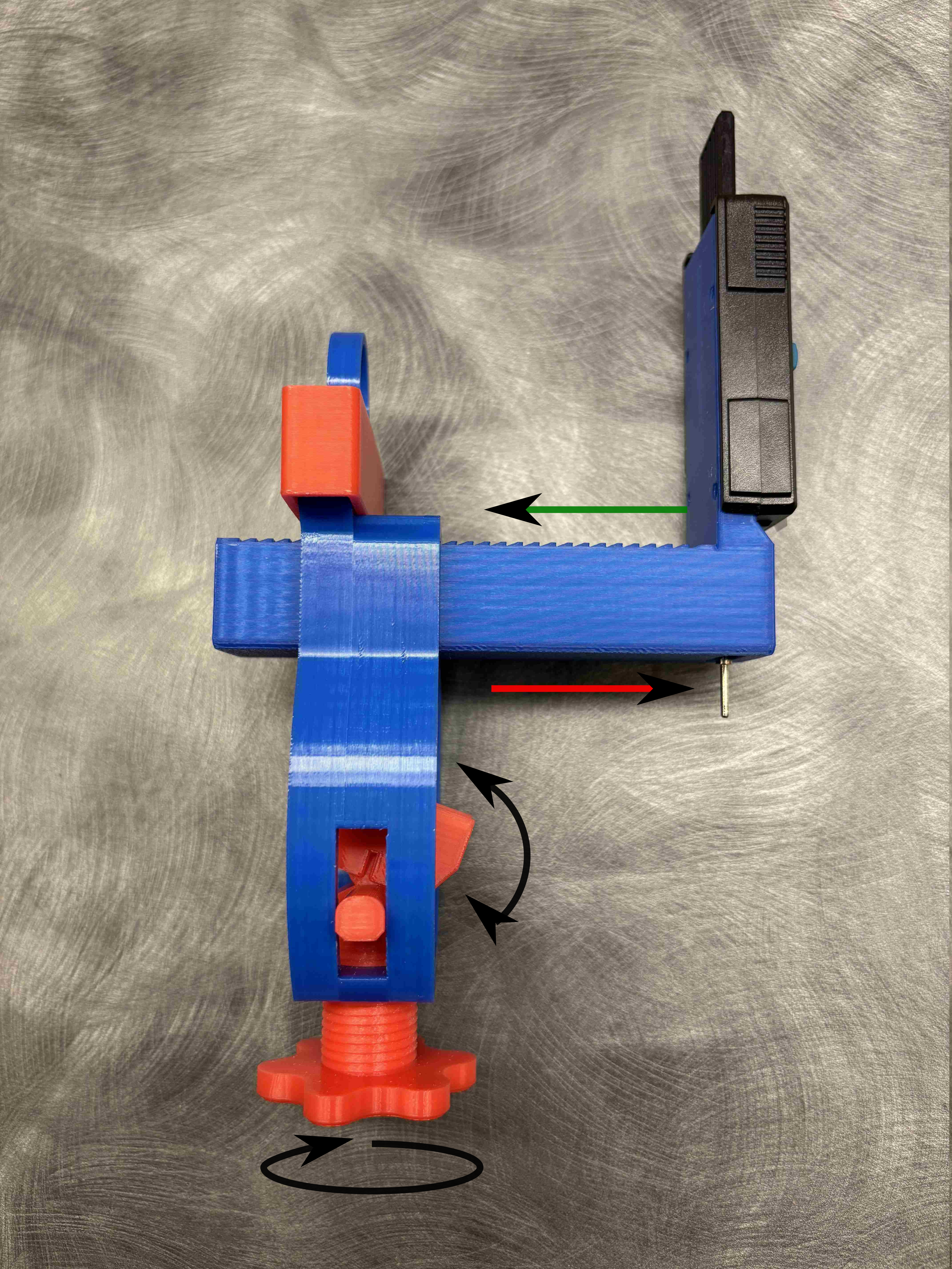
If the tip gauge wobbles in the direction of the red arrow, then decrease w. This affects measurement accuracy, so keep it tight.
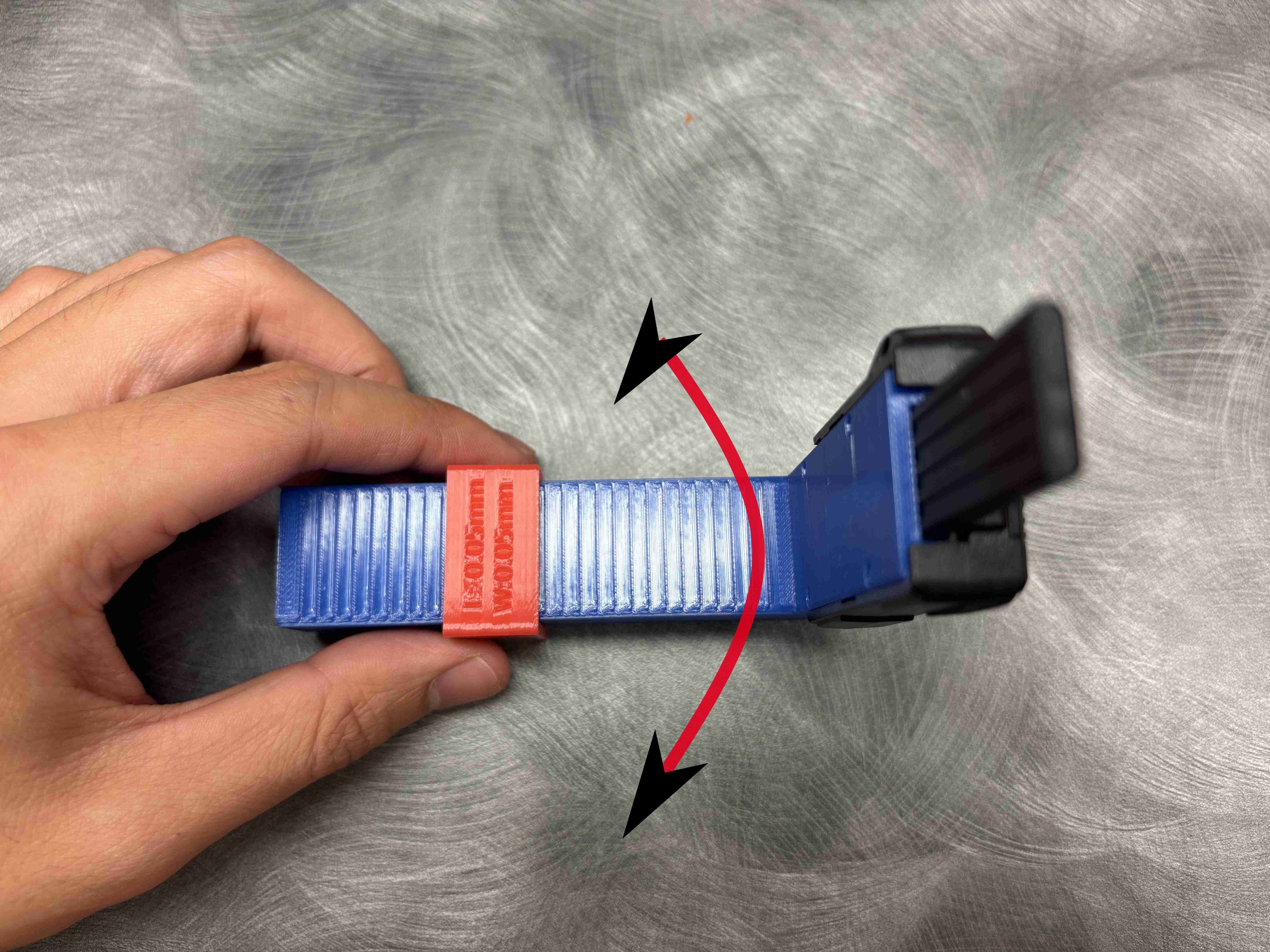
If the tip gauge wobbles in this direction, then decrease l. This does not affect accuracy as much, so do not overdo it.
3. Assemble the Slider Block and Spring Mechanism
After you find the best tolerance value, print the corresponding file under Slider block. These files use the format lx.xxwy.yy.stl. The x.xx and y.yy values correspond to the length and width tolerances you found with the blocks.
At this point you should also have printed everything from parts on the baffle tool Printables page. None of these parts require tolerance calibration.
Carefully remove all supports from the slider block and make sure there are no bits left behind. Use a utility knife or screwdriver to scrape the support surfaces flat.
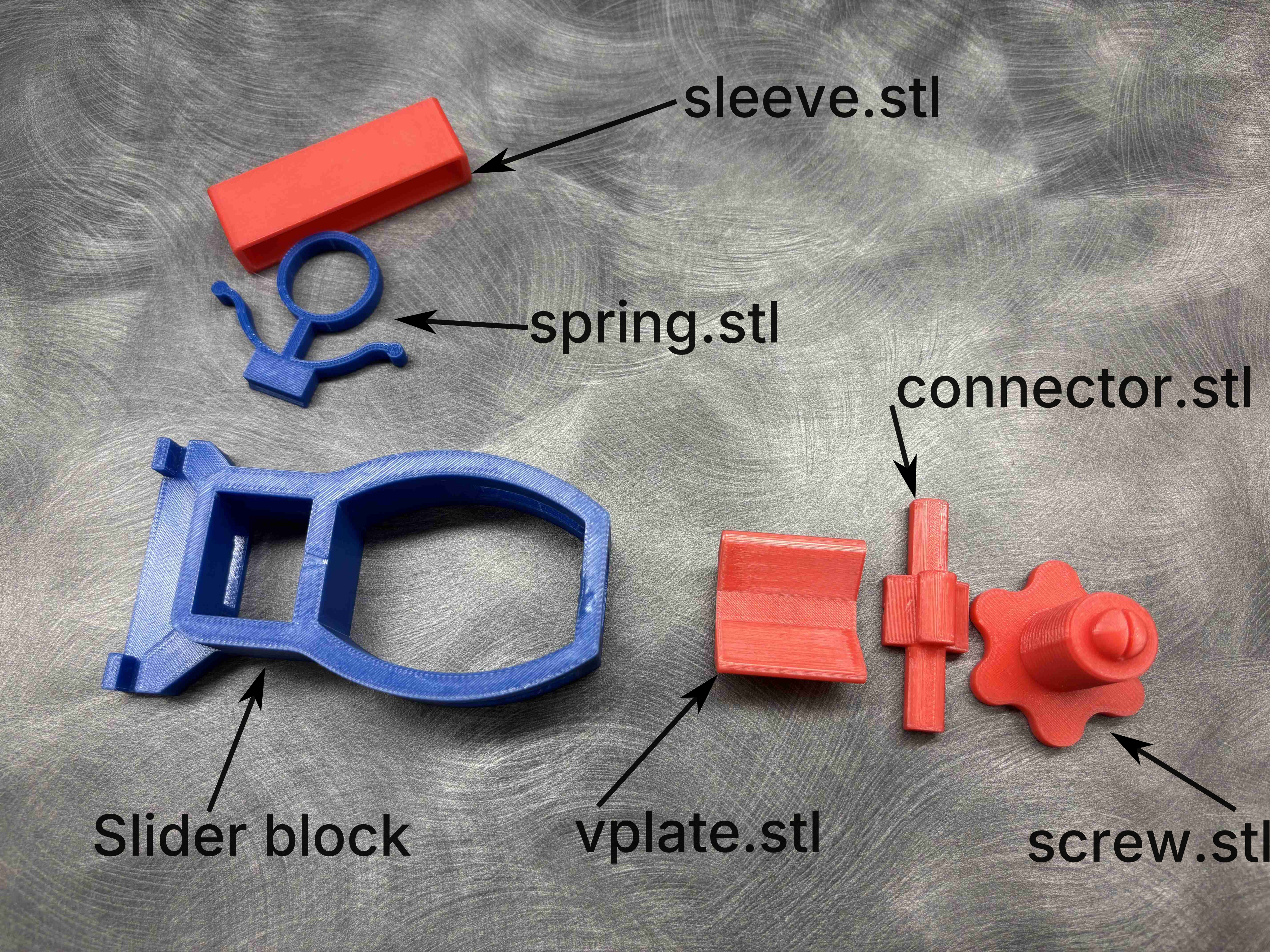
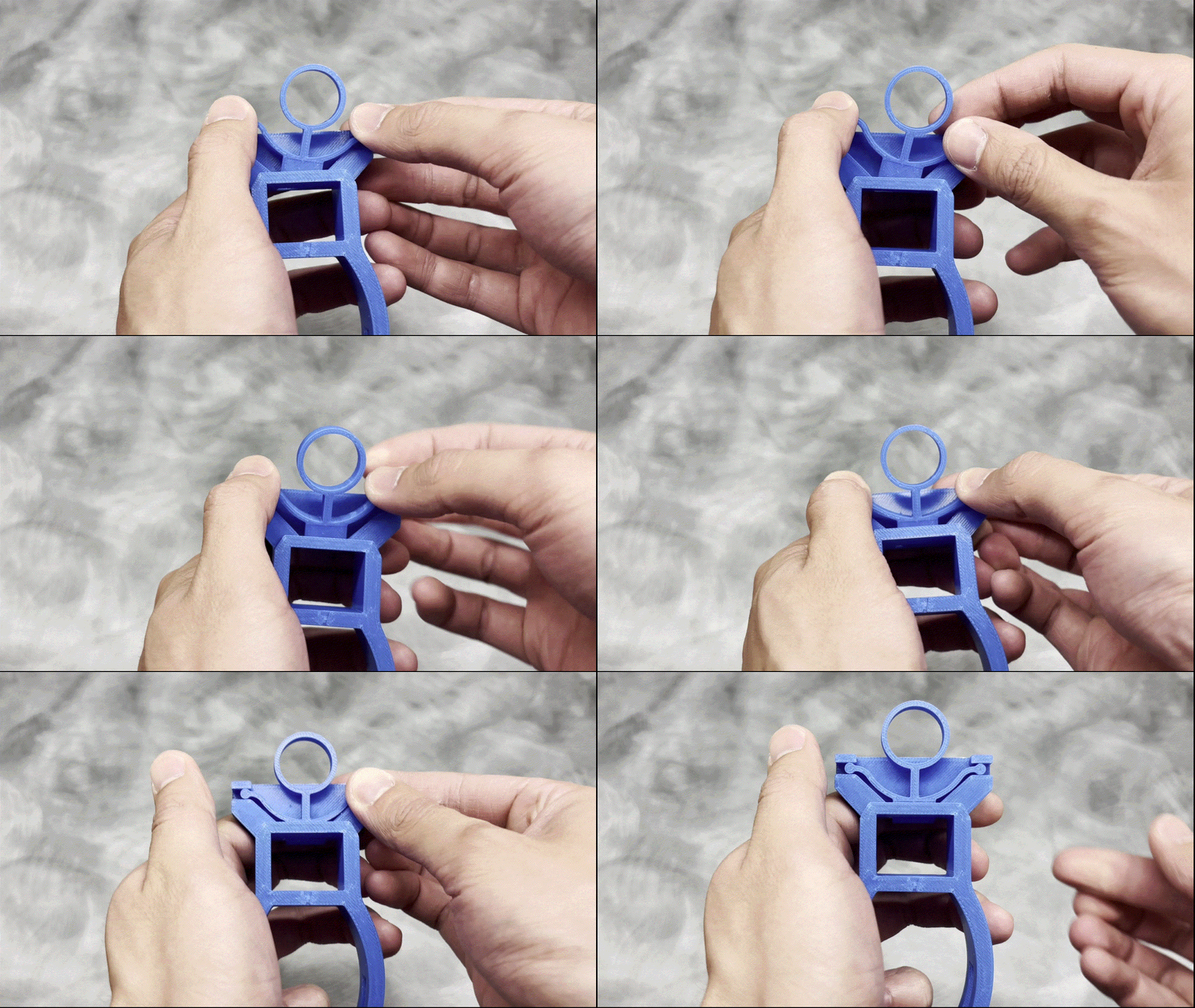
Slide the spring.stl into the slider block, and press it into place as shown below.
Note: The spring part is not symmetric. Make sure the small notch along the bottom edge of spring.stl is placed against the back of the slider block. If you print the parts in the default orientation, you should be facing the top print surface of spring.stl when you install it.
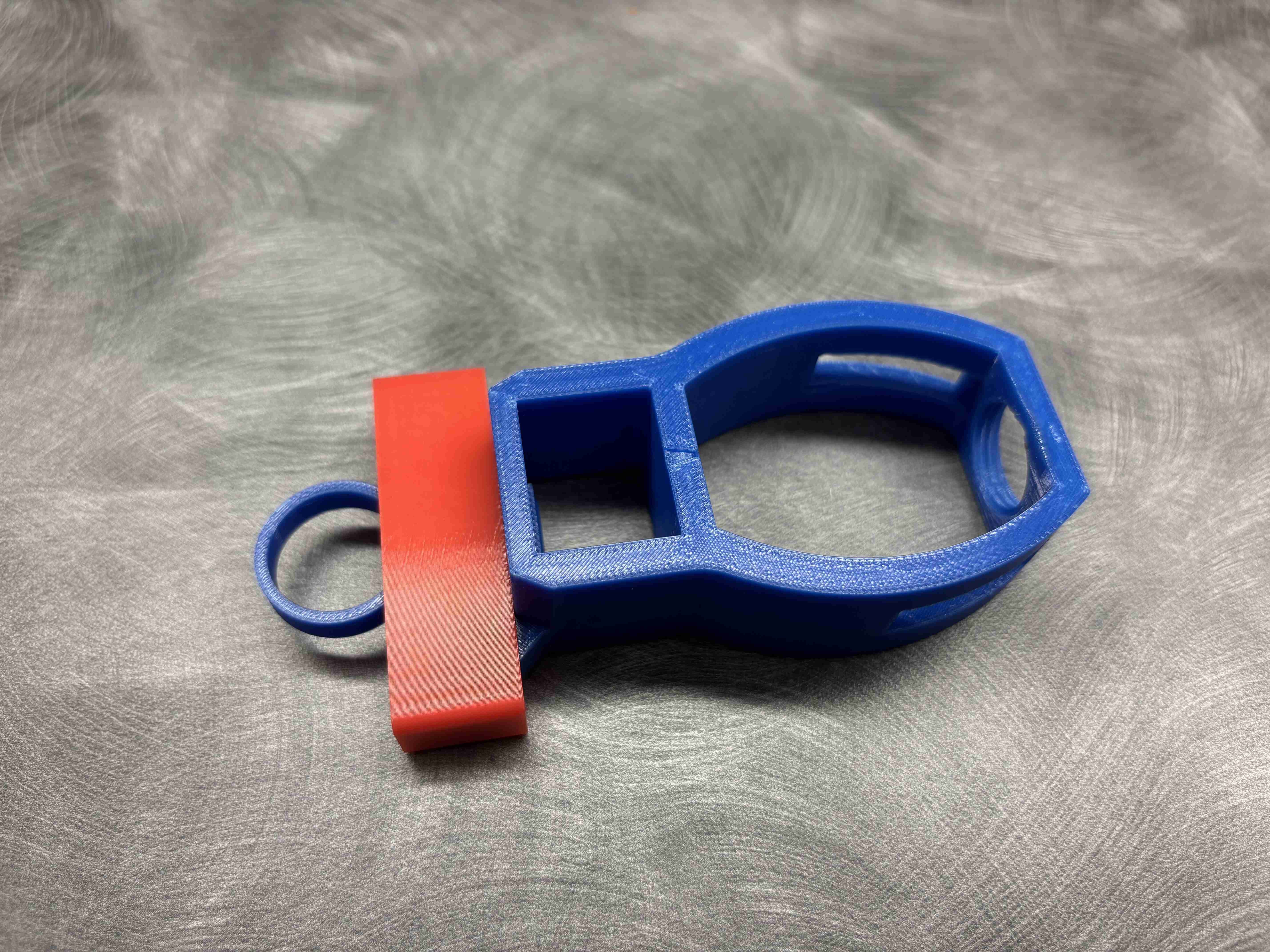
Then install sleeve.stl over the spring mechanism to hold it in place.
4. Install the V-Plate
Start by installing connector.stl into the slider block. Note the direction and make sure the bottom socket points toward the threaded hole.
Then screw screw.stl into the threaded hole. Align the sphere at the top of screw.stl with the socket at the bottom of connector.stl.
Press the two pieces together and the sphere should snap into the socket. This step requires some force. Stand the slider block upright on a sturdy surface, then press down firmly on the top of connector.stl.
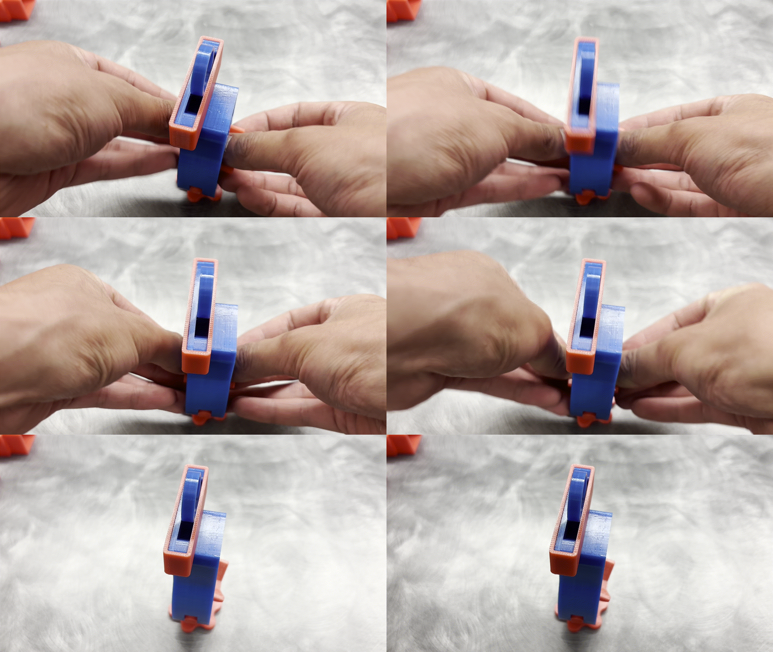
Then install vplate.stl in the same way by aligning the cylinder on connector.stl with the socket on vplate.stl, then press until it snaps into place.
5. Final Assembly
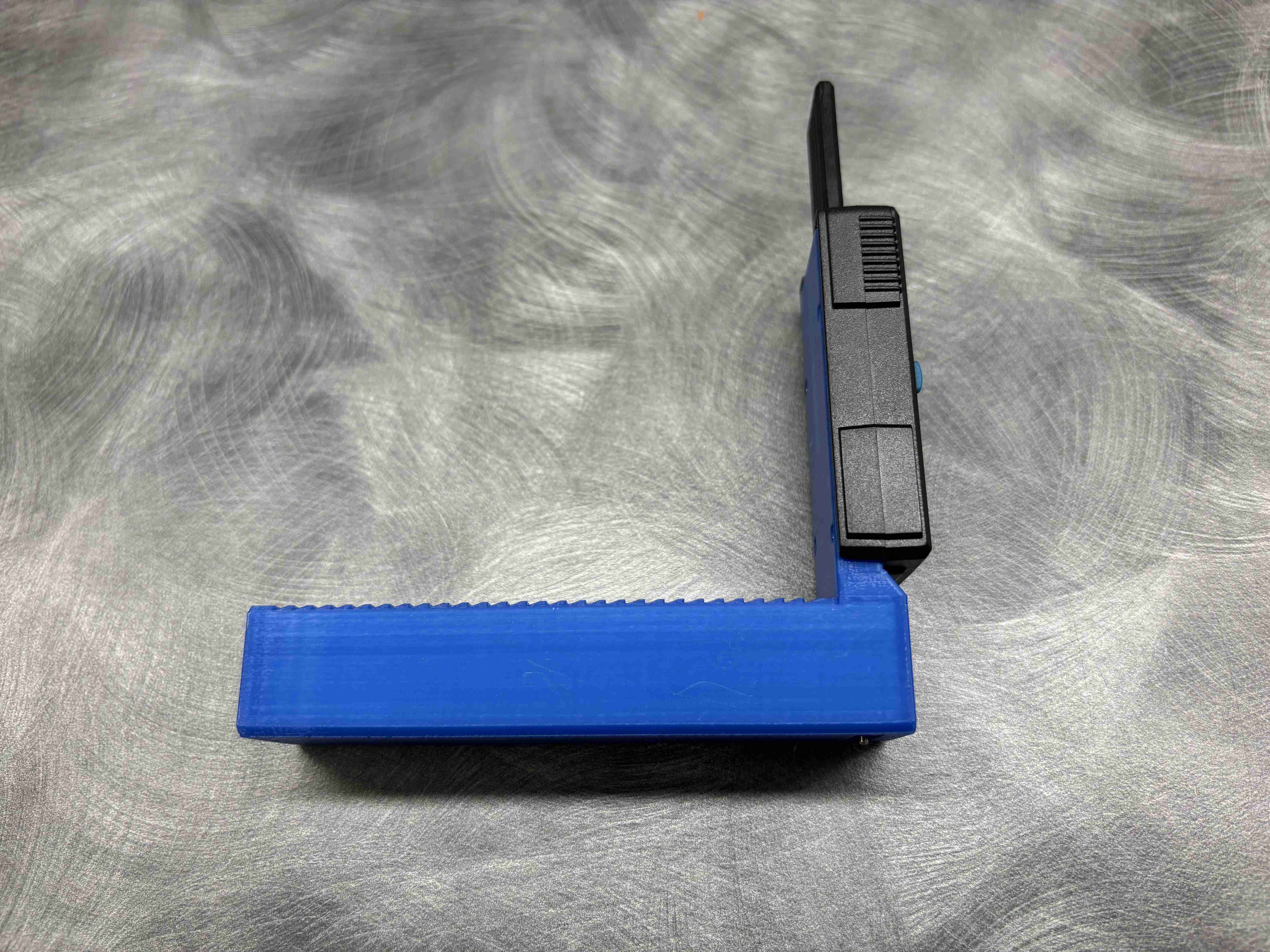
Pull up the ring on the spring.stl and slide the tip gauge into the rectangular slot on the slider block. The finished product should look like this.
Check these to make sure the assembly is correct:
- With the slider block held steady, if the
spring.stlis released, the tip gauge bar should not be able to move out in the red arrow direction. When the spring is lifted, the tip gauge should slide smoothly in either direction. - The gauge bar should be able to move in the green arrow direction. The spring will engage the grooves on the tip gauge bar, and it should click as it slides over each groove.
vplate.stlshould be able to rock back and forth in the direction indicated by the arrow. It should not be able to rotate in other directions.screw.stlshould turn freely. The entirescrew.stl+connector.stl+vplate.stlassembly should move freely as a unit.
Measuring the Baffle
1. Putting the Mouthpiece on the Baffle Tool
Lift the spring and remove the tip gauge. Put the mouthpiece between the v-plate and the slider block. Align the tab against the flat wall of the slider block.
Place the mouthpiece so that the entire window extends beyond the slider block. Align the center of the window with the center marking on the slider block to ensure that the gauge measures along the center line. Tighten the screw to hold the mouthpiece firmly in place.
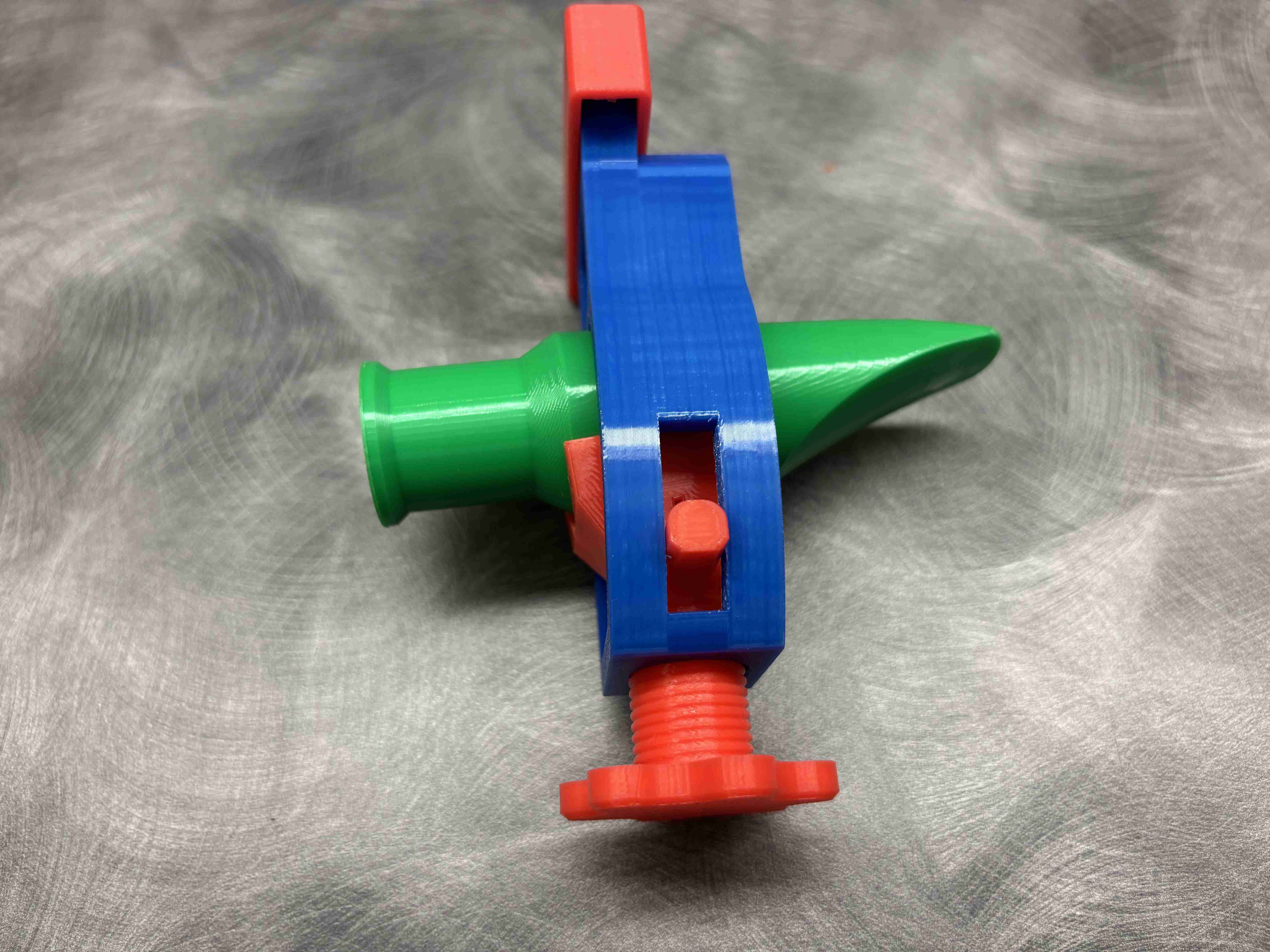
Place the mouthpiece into the slider block. The beak of the mouthpiece should point toward the opposite side of the spring.
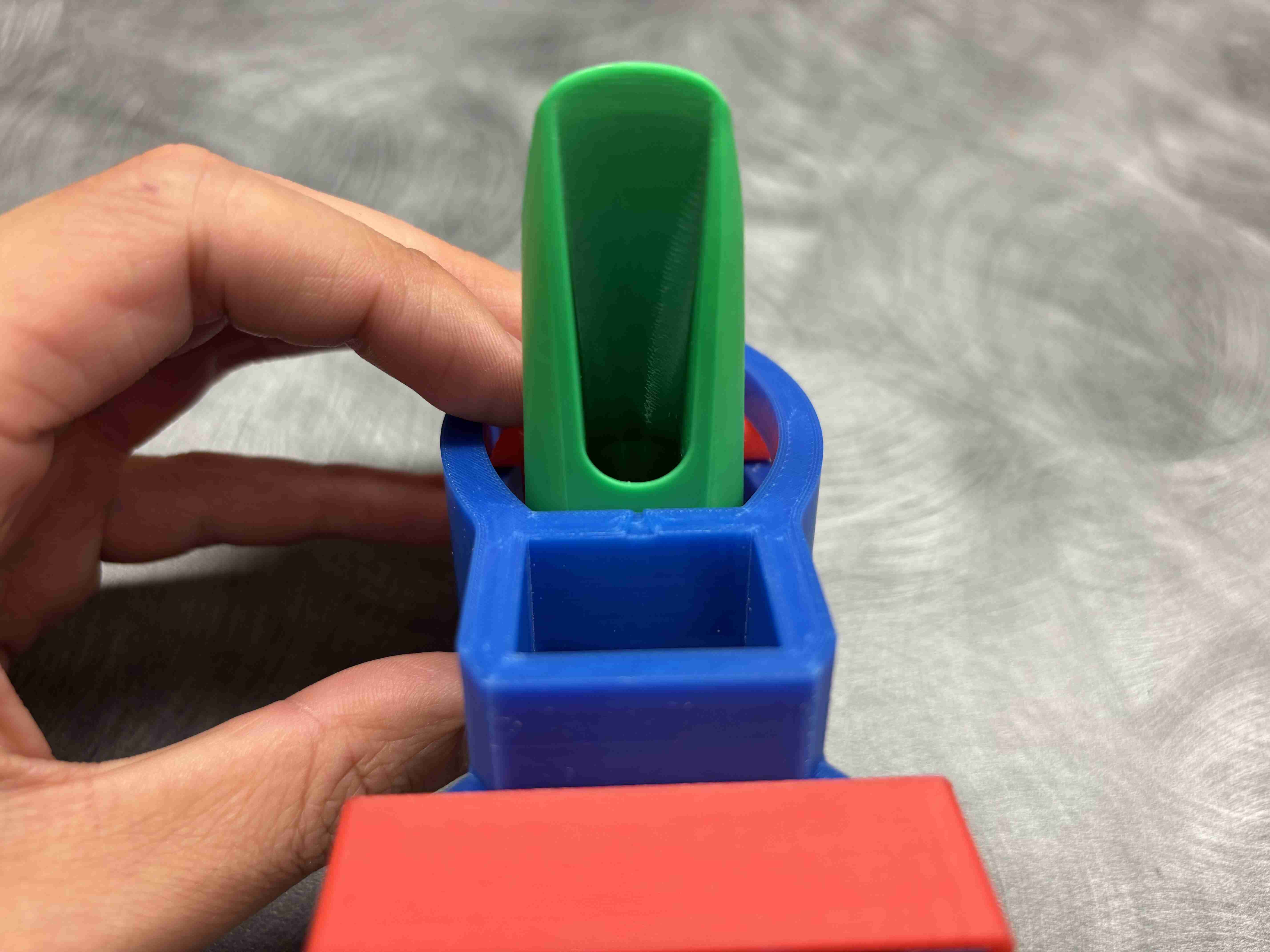
The small notch on the face of the slider block marks the center. Align it to the bottom of the window.
2. Align the Tip Gauge with the Mouthpiece
Reinstall the tip gauge and move it so that the probe is as close as possible to the tip rail.
Make sure the spring is fully engaged with the grooves. Do this by pushing the tip gauge against the grooves in the red arrow direction while holding the slider block. Keep the tip gauge in this position.
Loosen the screw slightly so the mouthpiece can move. Adjust the position of the mouthpiece so the probe aligns with the inner edge of the tip rail. Also make sure the probe is centered on the tip rail.
Lightly press the probe down until it contacts the inner edge of the tip rail. Zero the gauge here. Do not force the probe, since it could flex the gauge and damage the mouthpiece.
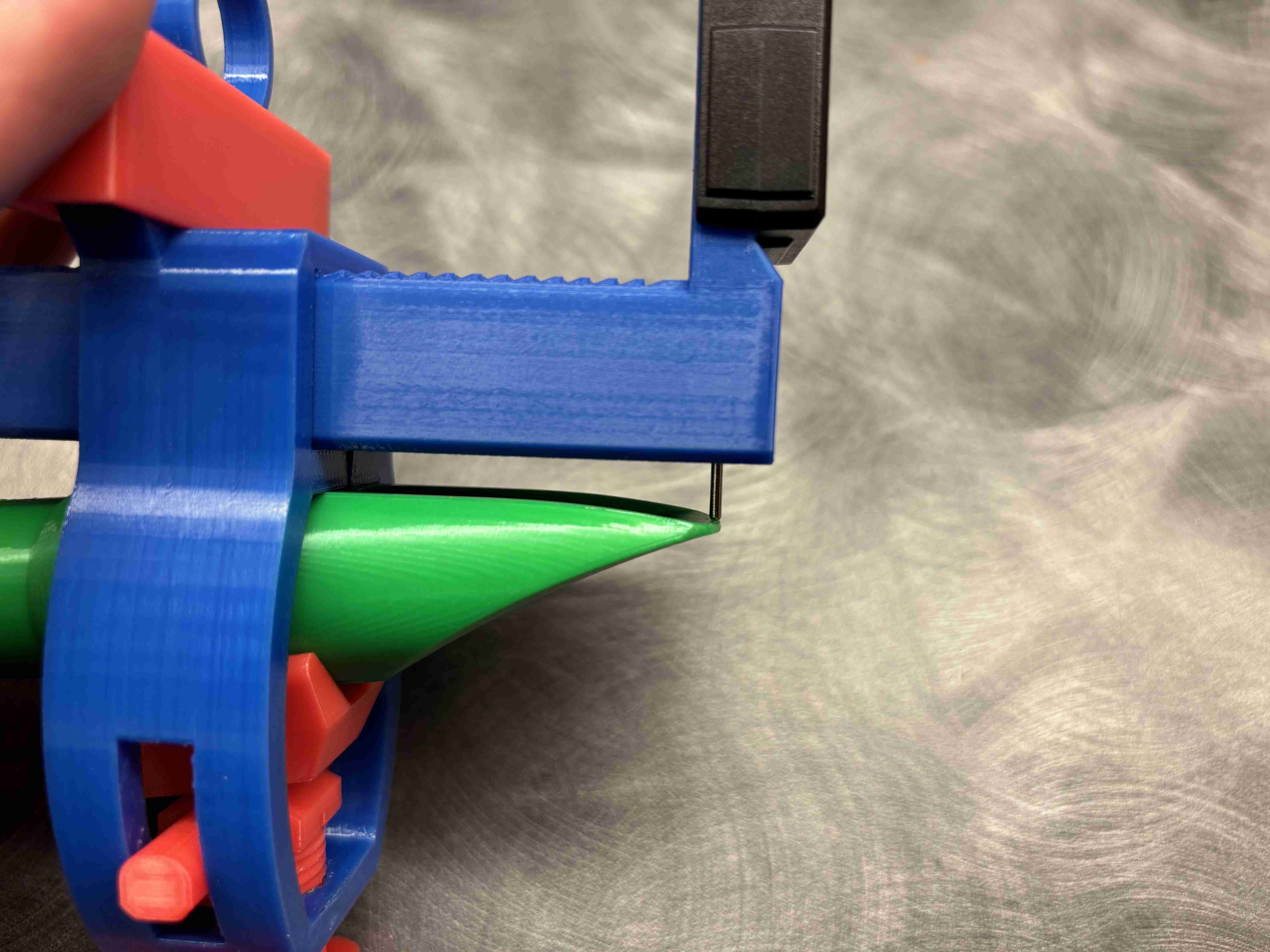
Adjust the mouthpiece so the probe aligns with the inner edge of the mouthpiece tip rail.
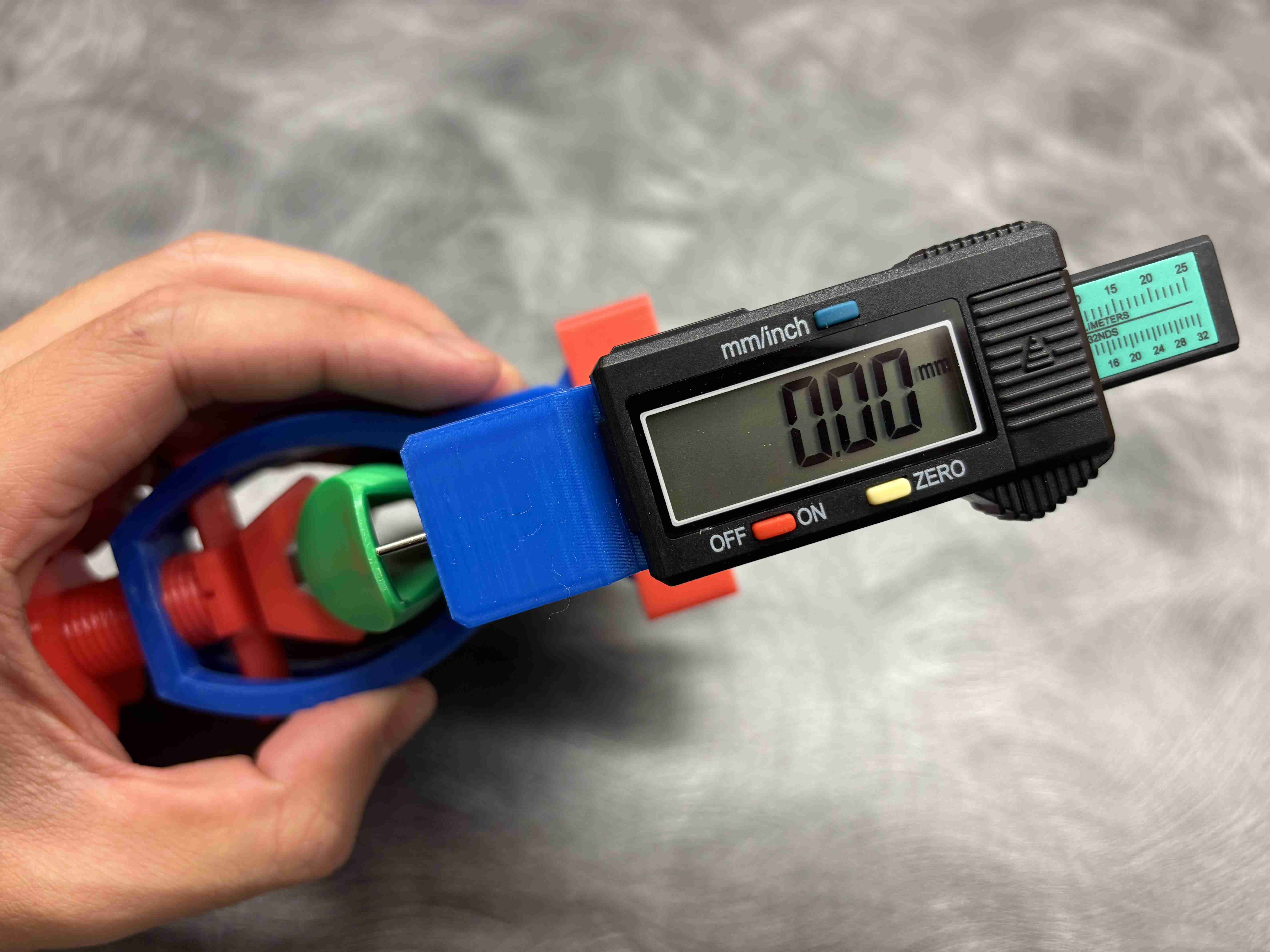
Zero the gauge and make sure the reading is set to 0.00 mm.
3. Measure the Baffle
Open mouthpiecelabs.com/design and go to the Baffle Measurement tab.
Move the tip gauge downward along the baffle by one groove. Stop after the spring clicks, then immediately push it in the other direction to lock it into the new groove.
Grooves are 3 mm apart. This information is built into the Baffle Measurement tab, so you don't need to keep track of it manually.
Lower the probe and visually check that it is still centered on the baffle. If it is not, adjust the gauge left and right, but do not move it forward or backward, and do not move the mouthpiece.
Lower the probe until it contacts the mouthpiece. Again, do not press with force. Make sure the gauge is in millimeters. Then enter the depth value into Depth and press Enter to add it.
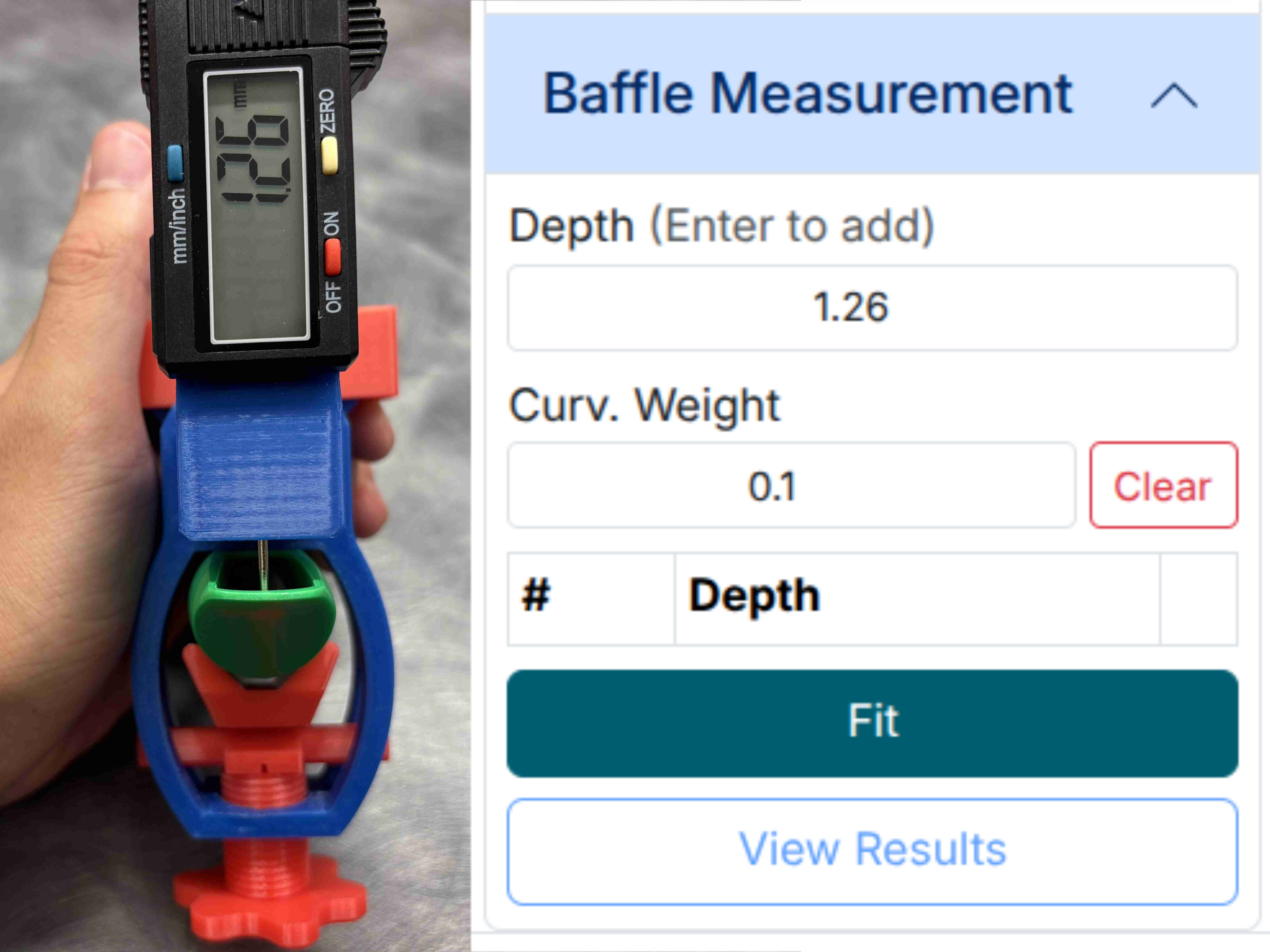
Repeat this process one groove at a time:
- Shift one groove.
- Pull back to lock in the spring.
- Take a measurement.
- Enter the depth value.
Continue until you reach the end of the window, the end of the gauge, or the point where the probe can no longer reach the baffle surface. In any of those cases, you are done with the measurements, and you can move on to the next step.
4. Compute the Baffle Curve
- Tip opening: by convention, measured in thousands of an inch. Set your tip gauge to inches. The tip opening value is the 3 digits after the decimal point. For example, a reading of 0.080 means the tip opening is 80.
- Facing length: by convention, measured in millimeters × 2.
- Baffle measurements: all baffle measurements should be entered in millimeters.
By now, you should have a list of measurements. They are also shown in the baffle curve image. The measurements should trace out the baffle curve of the mouthpiece you are measuring.
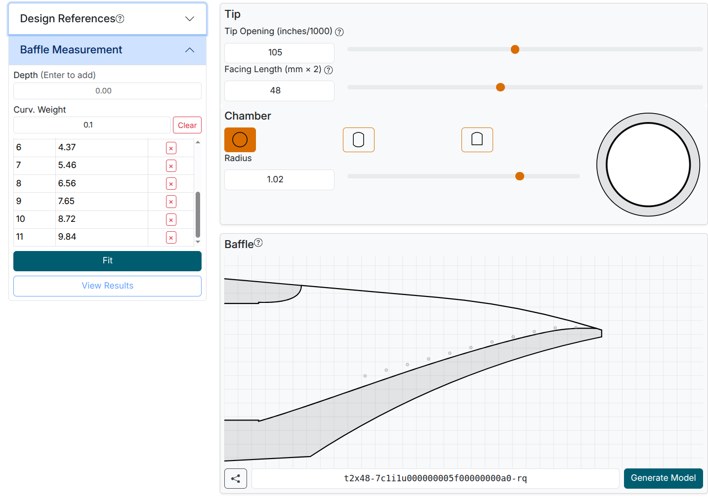
Before proceeding, measure the tip opening and enter it in the main Tip area. Do the same for facing length.
After the tip opening and facing length are set and all measurements are entered, click Fit to automatically compute the baffle curve for your measurements.
5. Baffle Computation Results
If the baffle curve fitting is successful, you will see the following window pop up:
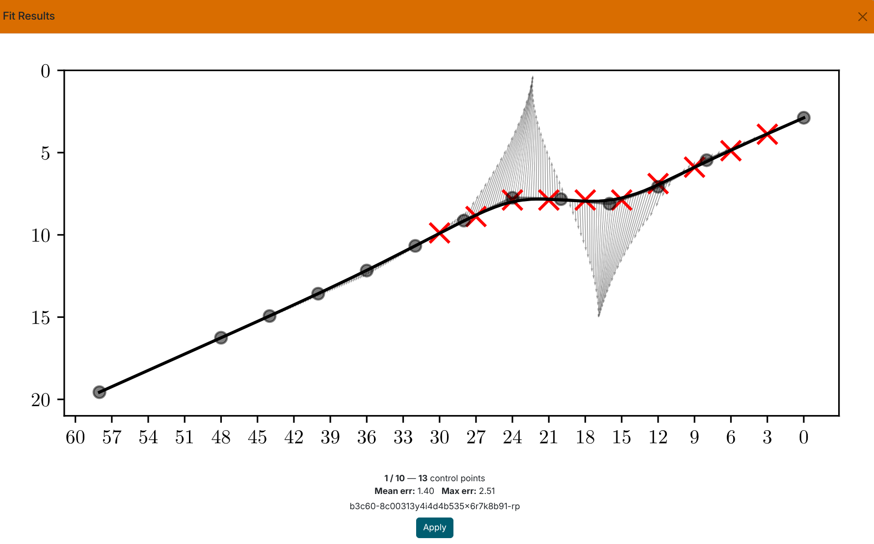
When you design the baffle, you move a fixed set of control points. The tool finds the best-fit curve for your measurements using a set number of control points. Fewer control points produce a simpler, smoother curve. More control points follow your measurements more closely but can cause erratic behavior between points.
The dialog shows 10 fits, ranging from the most detailed to the simplest. You can choose either a simpler or more complex curve. Navigate between them by clicking left or right on the chart.
Chart markings:
- Red X marks: your measurements
- Gray dots: control points defining the curve
- Black curve: the fit that will be applied to your design
- Hatching: shows local curvature. A consistent direction is good; constant switching between the two sides of the curve is a bad sign.
Look for a curve that follows your measurements without unnecessary bends.
Errors: Mean err / Max err are the average and worst-case deviations from your measurements. A mean error of 1 or below is very good. 1–3 is acceptable, and above 3 you should consider a curve with more points.
Avoid curves where:
- The hatching switches sides frequently. This indicates overfitting, where the curve is bending back and forth to chase individual points rather than the overall shape.
- Mean error exceeds 3.
Pressing Apply overwrites the facing curve in your current design with the selected fit parameters. You can also manually copy the code into any reference tab if you'd like to compare it with your current design.
Curv. Weight controls how much the solver prefers smooth, straight curves. The higher the value, the smoother the curves, at the expense of matching your measurements exactly. Sticking with the default of 0.1 is a good choice for most cases.
6. Next Steps
Now you have a digital copy of your mouthpiece's baffle curve. You can compare it with designs from our list of reference mouthpieces, or use it as a starting point for your creativity: more air? Increase the tip opening. Richer low notes? Drop the baffle near the chamber.